Engineering Note 01
I/O Positioning and Mechanical Clearance Considerations in Industrial PC Enclosure Design
How PCB edge distance, panel thickness, machining relief and cable space affect practical enclosure design
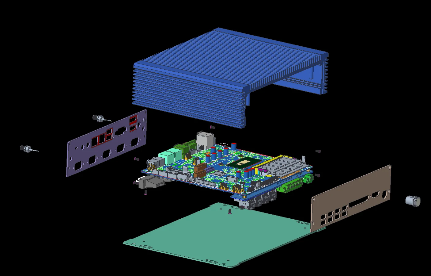
Good enclosure design starts with understanding the relationship between PCB layout, I/O position, panel structure and real assembly space.
1. Introduction
Industrial PC enclosure design is not only about matching motherboard dimensions. In a compact system, the position of every motherboard I/O connector can directly affect the rear panel design, enclosure thickness, machining method, cable routing and final assembly process.
A design may look correct in 3D and still become difficult to manufacture or assemble if the mechanical space around the connectors is not checked early. This is especially important for custom industrial PCs, where the same motherboard may be used in different enclosure structures or adapted to different customer requirements.
2. Why I/O Position Matters
One of the first dimensions to check is the distance from the motherboard I/O interface to the PCB edge. This distance determines how the connector aligns with the external panel and how much material can remain around the opening.
Sheet-Metal Enclosures
Sheet-metal panels are usually relatively thin, and stiffness is often created through bends, flanges and surrounding structure rather than panel thickness alone. For this type of enclosure, the I/O connector can often sit relatively close to the PCB edge, provided that the cutout, bend line and fastening structure still have sufficient clearance.
Machined Aluminum Panels / Aluminum Enclosures
Aluminum panels provide good rigidity, appearance and thermal performance, but the mechanical requirements are different. When a panel becomes wider, the thickness may need to increase to maintain stiffness and flatness. A thicker panel can then interfere with connectors whose housings sit close to the PCB edge.
In this situation, the designer may need to reconsider the I/O position, panel thickness, cutout geometry and internal clearance together. The goal is not simply to make the panel thinner or thicker, but to balance rigidity, machining feasibility, weight and connector accessibility.
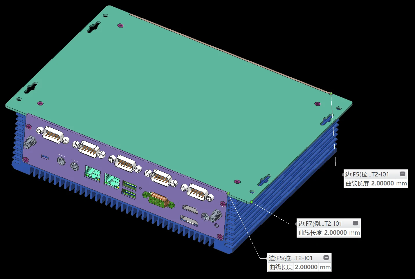
3. Rear I/O Clearance and Local Relief
A thick aluminum panel should not be treated as a flat wall with simple rectangular openings. Around motherboard I/O connectors, the back side of the panel may require local pocketing, chamfers or relief features so that the connector housing, plug body and locking hardware have enough space.
Key dimensions to check include:
- I/O connector height and housing width
- Distance from the I/O connector to the PCB edge
- Panel thickness around the opening
- Minimum remaining wall thickness after machining relief
- Tool access and machining radius
- Clearance for plugs, thumbscrews and locking screws
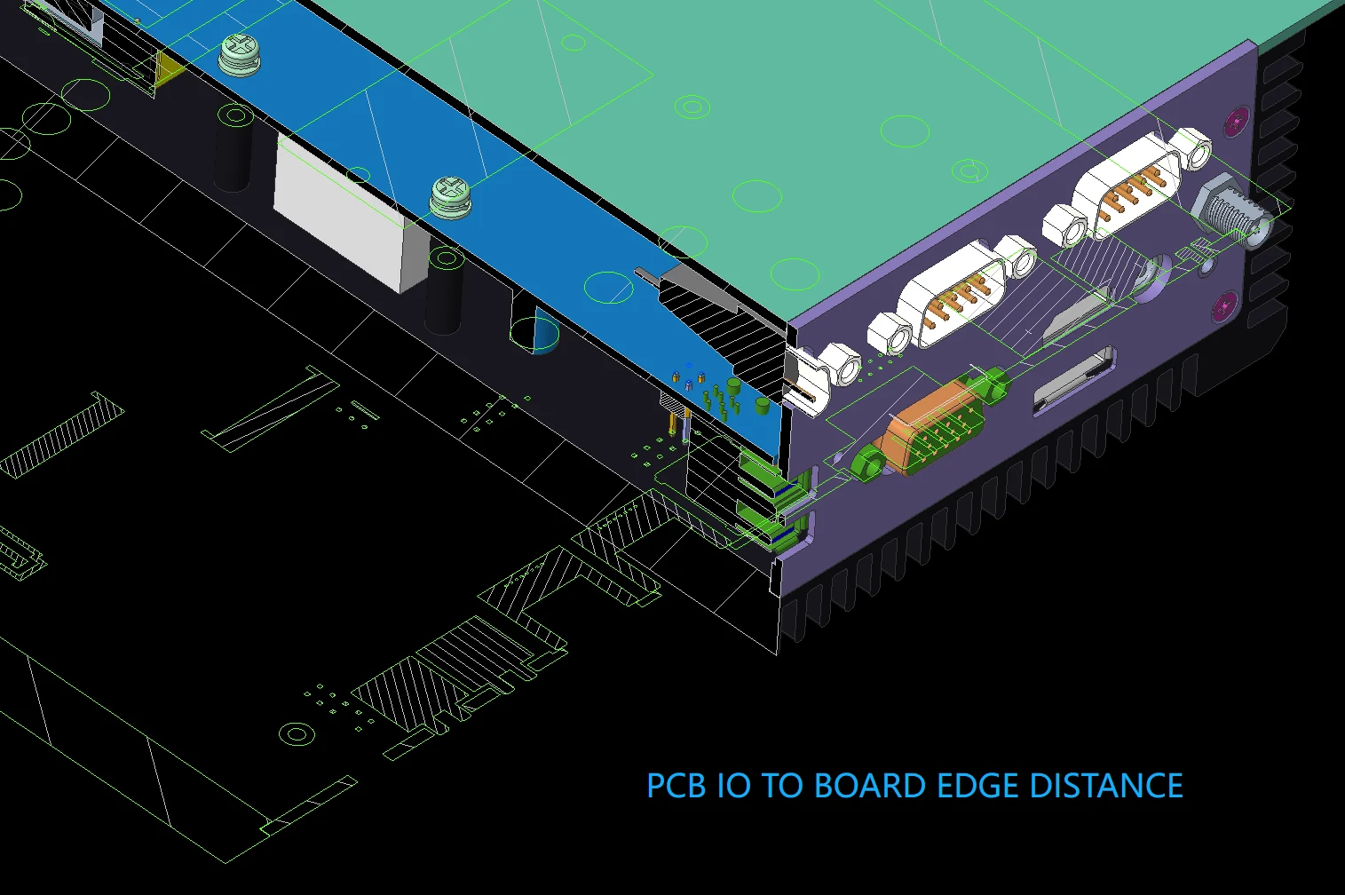
This is one reason why the I/O-to-board-edge distance may be different between motherboard designs intended for different chassis structures. The correct value depends on the enclosure architecture and the connector type; there is no single distance that is optimal for every design.
4. Cable Routing and Assembly Considerations
Clearance should be checked with the actual cables installed, not only with the bare PCB. SATA, COM, USB and power cables can occupy much more space than the connector body itself, particularly when the cable must bend immediately after insertion.
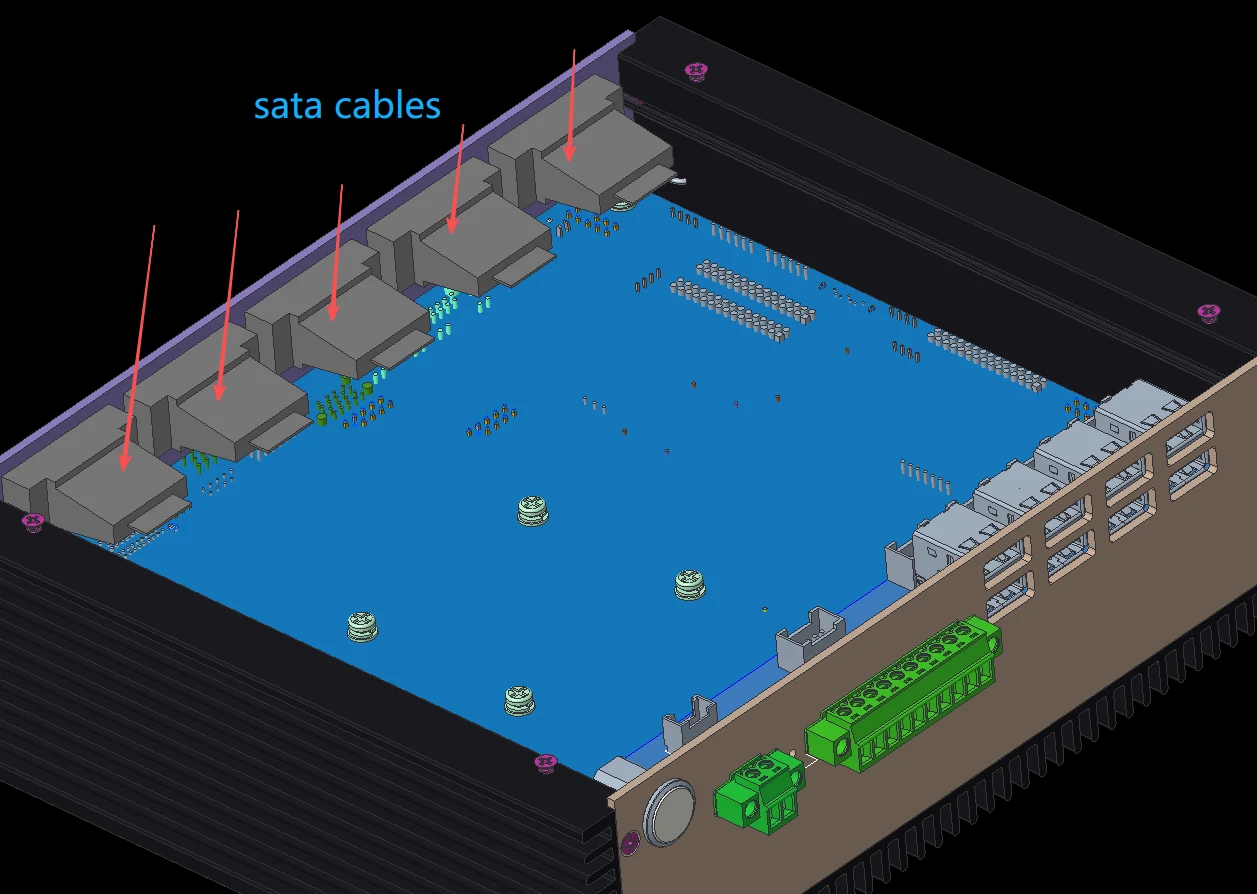
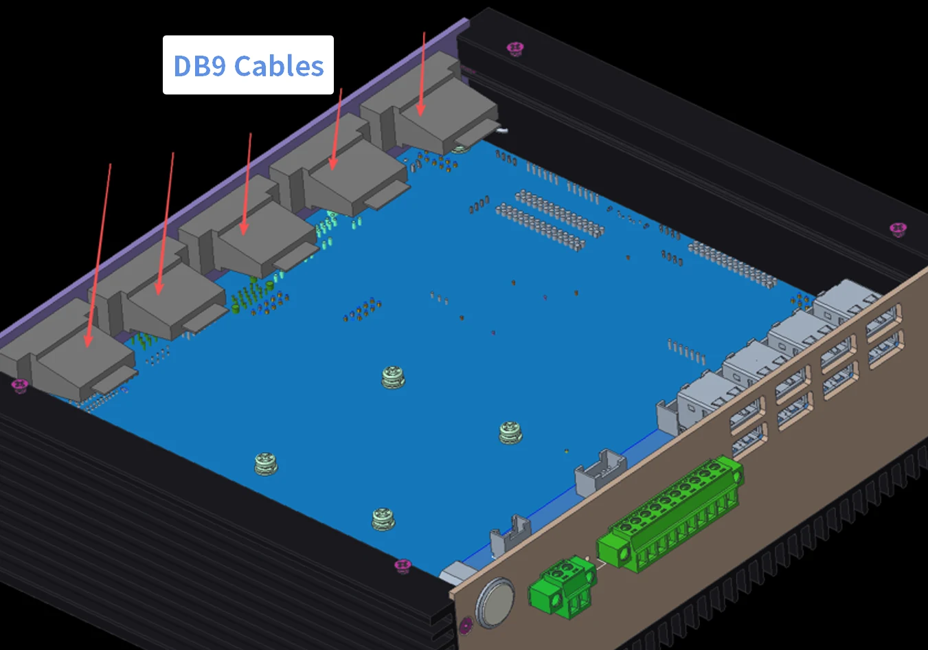
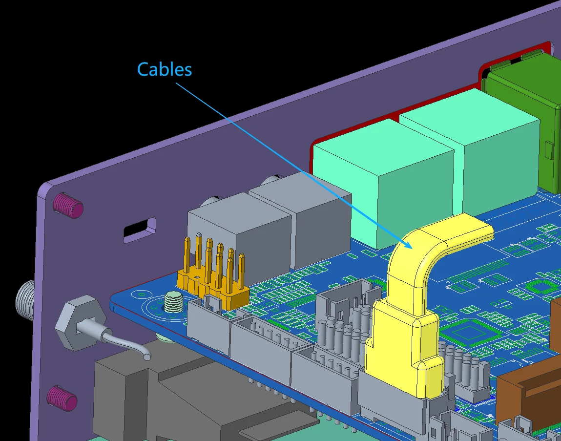
Figure 4. Example of SATA connector locations. Cable plug length, bend direction and service space must be included in the mechanical envelope.
Before finalizing the enclosure, reserve sufficient space for:
- Cable plug length and bending radius
- Connector insertion and removal
- Assembly tool access
- Cable routing after the top cover or side panel is installed
- Tolerance variation between cable suppliers and connector versions
If this space is ignored, the result may be cable stress, connector damage, difficult assembly or a cable that cannot be installed after the enclosure is fully assembled.
COM / DB9 Interfaces
DB9 connections require additional attention because the mating plug and screw-locking hardware extend beyond the panel. The designer should check plug height, cable exit direction, bending space and access for the locking screws. A cutout that looks correct from the outside may still be difficult to use if the internal or external service space is too tight.
5. Practical Design Verification Before Prototyping
A reliable mechanical review should be based on the complete assembly condition rather than the PCB outline alone. A practical verification sequence is:
- Confirm PCB outline, mounting holes and connector positions.
- Build the real connector and cable envelopes in the 3D layout.
- Check panel thickness, local machining relief and minimum wall thickness.
- Verify assembly sequence, screw access and cable installation direction.
- Review manufacturing tolerances before releasing the prototype.
- Validate the prototype with actual cables and mating connectors before mass production.
6. Design Checklist
| Item | What to Verify |
|---|---|
| PCB / I/O position | Connector location, housing size and distance to PCB edge |
| Panel | Thickness, cutout size, local relief, stiffness and flatness |
| Machining | Tool access, corner radius, remaining wall thickness and tolerances |
| Cables | Plug length, bend radius, removal space and routing direction |
| Assembly | Fastener access, installation sequence and serviceability |
| Prototype | Verify with actual cables, plugs and production-representative parts |
7. Conclusion
Good industrial PC enclosure design is not simply a matter of fitting the motherboard inside a box. The PCB edge distance, I/O connector geometry, panel material, panel thickness, machining relief, cable routing and assembly process must be evaluated as one mechanical system.
For custom projects, solving these details before prototyping can reduce rework, improve assembly efficiency and make the final product more reliable and easier to manufacture.
Domify Engineering Focus: Industrial PC mechanical design | Custom aluminum enclosures | Thermal and assembly optimization | OEM/ODM engineering support
Need mechanical review for your industrial PC enclosure?
Domify supports custom aluminum enclosure design, mechanical optimization, prototype verification and OEM/ODM engineering projects.
Discuss Your Project